Editor’s intro: The CS 9600 CBCT System has an intuitive interface and intelligent features that automate much of the scanning process, leading to reduced retakes and quality images, with low radiation exposure to the patient.
Dr. John Khademi illustrates the benefits of CBCT imaging for diagnosing and treating endodontic patients
Cone beam computed tomography (CBCT) has been allowing endodontists to practice at the highest level for the past decade, and we’ve seen more and more doctors adopting the technology as its benefits to diagnosis, treatment planning, and treatment are undeniable. However, new CBCT systems released within the past year utilizing the latest “smart”
technology have taken endodontic diagnosis, treatment planning, and treatment outcomes even higher. With its intui-tive interface and intelligent features that automate much of the scanning process, the CS 9600 (Carestream Dental) is
designed for doctors who are seeking to do more for their patients.
Advanced video and radiographic scouting aid in capturing the region of interest

Scout imaging has a long history of use with medical CT and is a welcome addition to the field of oral health. There are two aspects to scouting that go hand-in-hand: Reducing retakes due to misses and allowing a smaller FOV, which reduces patient dose. With the CS 9600, my technologists use both advanced video systems — not lasers — and radiographic scouts to more accurately target the imager on the desired structures. In fact, the scouting feature has eliminated retakes due to missing the desired structures in our office; in the months we have been using the CS 9600, we have not had a single miss. This ability to hit the target 100% of the time has allowed us to routinely use the smallest 4 cm x 4 cm FOV and reduce patient dose.

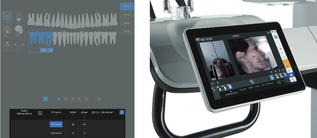
For many studies, we simply select the appropriate FOV using the letter matching on the target area on the bite tab and confirming the area with the two video feeds (Figure 1). Small adjustments in the anteroposterior (AP) and crainiocaudal (CC) directions, as well as the center-of-rotation, are easily accomplished using the live camera feed. We’re finding that center-of-rotation is a little trickier, and the feed from under the chin really helps with this adjustment. The two systems can be used in concert as well, with a radiographic 2D scout showing the AP and CC dimensions of the FOV, and then a center-of-rotation adjustment with video. For tricky setups with unusual arch-forms or unusual tooth positions, the full 2D and SmartAuto 3D scouts produce a perfect shot ever time. The combination of these two scout views shows the AP and CC dimensions of the FOV, and the exact center-of-rotation on the patient as they are positioned in the system.
High resolution and larger FOVs support multi-specialty diagnosis
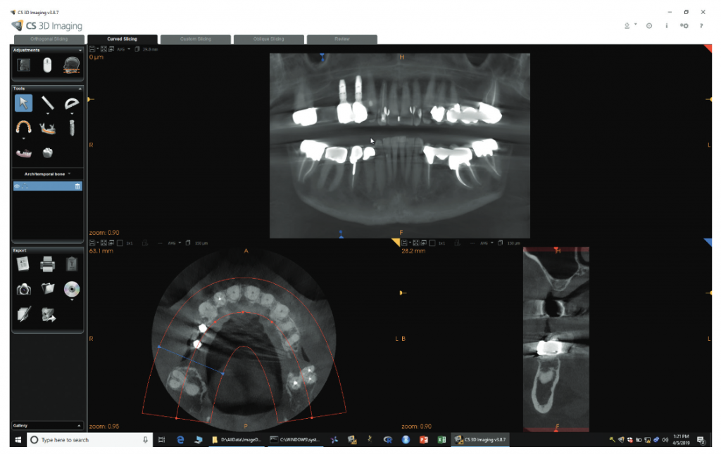
While most endodontists don’t often work with larger FOVs, that doesn’t mean there aren’t situations when it’s incredibly beneficial. Just this week, I had a long-time patient on whom I had performed several endodontic procedures in all four quadrants and wanted to follow up on those teeth. She also reported that she had three implant procedures done in the URQ several years ago, one of which had failed. With the ability to do larger FOVs at high resolution, the CS 9600 made it easier to get all the follow-ups I needed at endodontic resolution, as well as to provide the implant surgeon with a new, high-resolution view of the potential implant site to re-evaluate in one quick scan (Figure 2). This can also facilitate referral-based imaging for colleagues.
A 120 kV generator plays a significant role in quality of images
There is very complicated relationship with kVp, mAs (milliamp seconds, pronounced “mass”), and filtration on image quality and patient dose. On one end, higher kVp and mAs generally result in higher quality images but at an increase in patient dose. Increasing mAs linearly increases dose — that is, increasing mAs by 25% increases dose by 25%, and doubling the mAs doubles the dose.
The relationship with kVp is more complicated because of filtration. A simple increase in the kVp increases patient dose; however with the CS 9600, the increase in kVp is accompanied by an increase in filtration after 90kVp (Figures 1A, 4A, 4B, 5A, and 5B). This reduces dose dramatically. What this nets out to for the clinician is similar, identical, or often improved image quality at a lower dose to the patient (Figures 3A and 3B).
Patented algorithms aid with Metal Artifact Reduction (MAR)

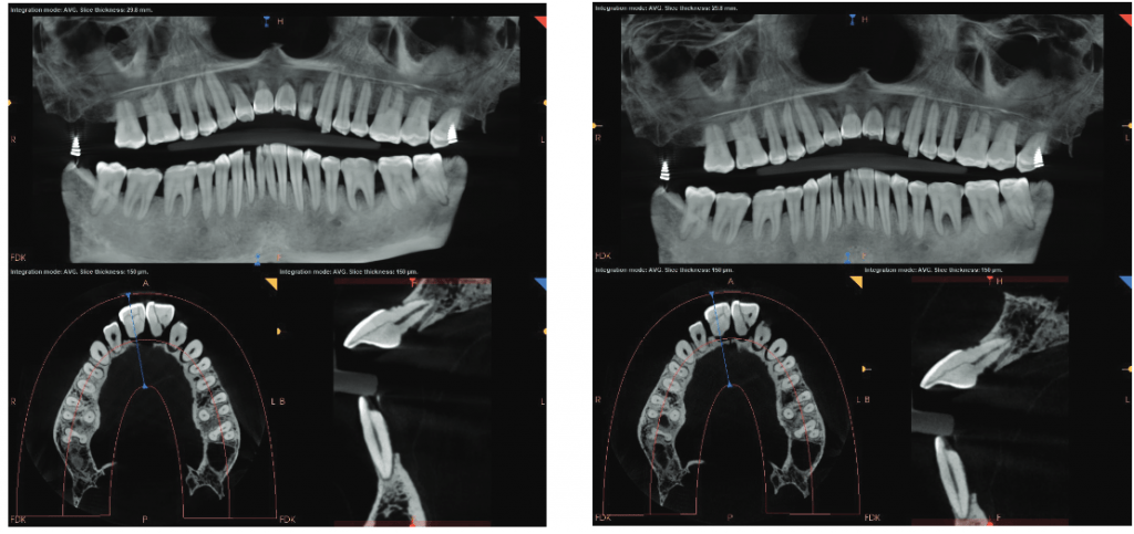
Dental and especially endodontic imaging is confounded by the presence of highly attenuating materials in the planes of interest.1 These highly attenuating materials create a number of artifacts with CBCT images that have no analog with projection radiography and have led to many errors in interpretation in textbooks, lectures, and research. That said, any means to improve image quality and reduce the appearance of these artifacts is always welcome, and I was delighted that the CS 9600 has two separate algorithms for CBCT study reconstruction — the traditional Feldkamp-Davis-Kress (FDK) and a second patented Metal Artifact Reduction (MAR) algorithm. This is implemented in software in two ways: 1) switching between the FDK and MAR algorithms for the entire study; 2) a highlighter type tool that shows the alternate algorithm as the mouse is moved around in the study.
As an example of the value of the larger FOV and MAR, the patient in Figure 8 presented with left-side pain not localized to any particular tooth. He reported cold and pressure-biting sensitivity as well as more recent heat sensitivity. The clinical testing was equivocal, with teeth Nos. 12, 15, and 17, responding to cold while tooth No. 18 and the previously treated mesial root of tooth No. 19 were not responding to cold. Teeth Nos. 15, 17, and 18 were all percussion-sensitive, consistent with clenching/grinding and their terminal positions in the arch. Projection radiography was unremarkable. I ordered a half-mouth study to see if there were any findings at CBCT (Figure 8). Tooth no. 15 had a finding that was likely artifact, but could have been resorption (Figure 6A). Switching to MAR shows that it was artifact (Figure 6B). Tooth no. 18 had a small radiolucency consistent with recent pulp necrosis (Figure 8). Other structures in the area were WNL.


Smart features recall patient para-meters for faster follow-up exams

Another great feature of the CS 9600 is its ability to “memorize” patient positioning to deliver highly reproducible studies for evaluating interval change. Interval change is the language used to describe comparing two studies taken at different times to evaluate things such as radiographic evidence of healing of an endodontically treated tooth; bone growth in an extraction site in treatment planning a possible implant; or the progression of a resorptive defect on a tooth. A second advantage is that tricky setups and difficult-to-image patients may be adjusted from the previously known position in an earlier study to a slightly altered position to optimize the study in a subsequent study.
My experience with the CS 9600 has changed the way I diagnose and treat patients, as well as my relationship with referrals. There’s no doubt that introducing a CBCT system to the endodontic practice will take doctors to the next level of care, but the advanced intelligent features of this newest system help doctors reach the pinnacle.

The CS 9600 CBCT has received recognition for “challenging conventional thinking with their game-changing products.” Read more about it here.
Stay Relevant With Endodontic Practice US
Join our email list for CE courses and webinars, articles and more..

