In his third article of the series, Dr. Tony Druttman discusses imaging methods

There is no doubt that radiography is one of the cornerstones of endodontics. We use radiographs to aid diagnosis, during endodontic treatment, to judge the quality of the root treatment we have just completed, and to monitor healing.
We live in exciting times in dental radiography. Having moved from the bisecting angle technique to the long cone paralleling technique for periapical radiography, in the last decade, there has been a shift from wet film radiographs to digital, with the quality of the digital image improving all the time. Most recently, cone beam CT scanners have been introduced to dentistry and have proven to be an invaluable aid to diagnosis.

Whatever the purpose of the radiograph, the aim is to get consistently high quality images, with the minimum radiation dose, and nowhere is that more important than in endodontics. There are many ways that this can be achieved with an existing X-ray set. Interpreting the information from a radiograph is notoriously subjective; different examiners won’t always agree when examining radiographs at different times, let alone with each other.
In endodontics, it is crucial that we get the best possible image (Figure 1), and that is usually achieved with the long cone paralleling technique, using some form of receptor (film or sensor) holder and aiming device.
Let’s look at the variables that can help you achieve that goal:
- receptor size and orientation
- receptor angle
- exposure.
Receptor size and orientation
When using films for intraoral periapical radiography, all the textbooks recommend size 1 (child) films in the vertical or portrait orientation for the anterior teeth and size 2 (adult) in the horizontal or landscape orientation for the posterior teeth. There are many situations when deviating from those recommendations can prove very advantageous. Where there is a large lesion associated with an anterior tooth, the complete lesion may not be captured on a small receptor, so if there are no anatomical constraints, a large film can be used (Figures 2A and 2B).
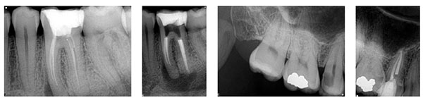
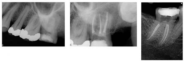
If it may not be possible to capture a tooth with long roots on a horizontal receptor, the receptor can be rotated from horizontal to vertical orientation (Figures 3A and 3B). Premolar teeth can be very difficult to radiograph using a size 2 horizontal receptor because of their position in the arch, the shape of the palate, and obstacles such as tori. Using a size 1 receptor in the vertical orientation will often overcome these difficulties (Figures 4A and 4B). Many patients with small mouths find the larger receptors very uncomfortable, and with some their use is not possible because of a gag reflex. Using a size 1 receptor in horizontal orientation will capture the image better than a size 2, because a more parallel image can be achieved, and it may well overcome the gag reflex (Figures 5A and 5B).
Receptor angle
The position of the receptor can be fine tuned by altering its vertical or horizontal angulation. Horizontal angulation should be changed when root separation is desired (Figure 6), i.e., looking at both roots of an upper premolar or both canals of a lower molar without superimposition. If the front of the receptor is angled mesially, the palatal or lingual root is thrown mesially, and the buccal root is thrown distally. Vertical angulation is changed to get a parallel view of a divergent root. Upper molars are the classic example: when the paralleling device is lined up with the buccal roots, the palatal root is foreshortened, the root tip may be cut off, and its relationship with the periradicular bone may be obscured because of superimposition of the zygoma. The change of angulation in either a horizontal or vertical direction need only be a few degrees. Excessive alteration will obscure the image, because the X-rays have to penetrate too much bone.

Exposure
The only setting on the X-ray set that is likely to be altered for every patient is the exposure timer, and the guide on the control panel is used to adjust the time. This will only give a dose based on an average for the tooth type, without taking into account bone density. The X-rays are likely to have penetrated through far more bone in the maxilla of a 6-foot rugby forward than a small 70-year-old lady, so the timer should be adjusted accordingly. Often the exposure has to be increased slightly to improve image quality for endodontics.
Film or digital
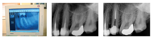
The number of practitioners using digital radiography is increasing. I see that in my own practice as the number of films sent by referrers is reducing. Film has always been the benchmark of image quality and is obviously cheaper. There is, however, a continuous supply of chemicals to be bought and disposed of responsibly. Digital radiography, on the other hand, requires a significant capital investment, but has so many advantages over film. The image quality is continuously improving. Radiographs can be read instantly and are a great communication tool. There is nothing better than showing the pre-op and post-op together or the pre-op and review image that shows healing to convince your patient that endodontic treatment is worth the investment. Archiving is easy, and provided you back up, you will never lose a “film.”
Although the transition from film to phosphor plate may be considered to be easier than CCD/CMOS, because the sensors have the same dimensions as film, they do not last and get easily scratched, making them progressively more difficult to read. For endodontics, and to my mind all radiography, the power of digital radiography is in the ability to read the image instantly while the holder is still in the mouth and make changes accordingly.
I am an unashamedly enthusiastic user of Schick Sensors. I have used both CDR and more recently Elite sensors, and I use both size 1 and 2. The image quality, as you can see, is superb.
The technique I use is a follows:
- At the intraoral examination, look at the position of the tooth or teeth in relation to other anatomical structures, shape of the palatal vault, curvature of the arch, presence of tori, etc.
- Decide which sensor to use and in which orientation, vertical or horizontal (remember that although the size 1 is easier to use, you have to be much more accurate).The patient’s height is sometimes a good indication of the length of the roots.
- Estimate the best exposure assessing body type and bone density.
- Position the aiming device /receptor holder carefully and press the timer.
- While the device is still in the same position (tell the patient not to remove it until you are ready), assess the image.
- If it gives an acceptable, but not an ideal result, make a note of which parameters to change for the next radiograph. If it is not acceptable, change the variables (exposure time, sensor size, and orientation, vertical and horizontal angulation), and repeat.
The radiation dose with the CCD/CMOS sensors is considerably reduced compared to the dose required for a film, and it is perfectly justifiable to repeat an exposure while adhering to the ALARA guidelines if the result is not of diagnostic value. Make a note of the exposure used so that when you review the endodontic treatment, the radiographs can be compared “like for like.” Also look at the postoperative result before you take your review radiograph so that you can set the aiming device in the same position.
CBCT
The most recent addition to the radiographic armamentarium in endodontics is the cone beam CT scanner. For use in endodontics, the small volume scanner like the Morita Accuitomo is an excellent unit. The ability to read radiographs in three planes opens horizons that were previously unimaginable. The full extent of resorptive lesions can be assessed, and lesions and structures that are hidden on the conventional periapical are fully visible (Figures 11 and 12).

Next issue: Rubber dams
 Endodontic specialist Tony Druttman, MSc, BChD, BSc, has extensive expertise in treating dental root canals, resolving difficult endodontic cases, and saving teeth from being extracted. His two London, England practices, one in the West End and the other in the City of London are restricted to endodontic treatment. www.londonendo.co.uk.
Stay Relevant With Endodontic Practice US
Join our email list for CE courses and webinars, articles and more..